
This topic explains how to add the xamDiagram™ control to a WPF application.
The following topics are prerequisites to understanding this topic:
This topic contains the following sections:
To add a xamDiagram control to your page, you need to create an instance of the control and add it to your page’s root element. The control is pre-configured to have a white background and takes the size of the container it has been placed into. Nodes with various shapes can be then added to it, as well as two types of connections – straight lines and right-angled lines with various configurable end caps. Apart from configuring connections between different nodes, xamDiagram allows for creating stand-alone connections which can be placed at an arbitrary place on its surface.
When adding diagram nodes in XAML, they are added to the Items collection of the diagram. The Items property is marked with the ContentPropertyAttribute.
The arrow-pointed lines visualizing the activity flow are configured as DiagramConnection objects.
Following are the general requirements for adding xamDiagram .
NuGet package reference:
Infragistics.WPF.Diagram
For more information on setting up the NuGet feed and adding NuGet packages, you can take a look at the following documentation: NuGet Feeds.
Namespaces:
A reference to the Infragistics® namespace: (xmlns:ig="http://schemas.infragistics.com/xaml")
Following are the general conceptual steps for adding xamDiagram .
Adding the xamDiagram control
Adding the nodes
Adding the connections
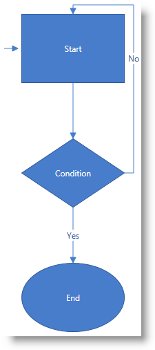
The following procedure walks you through the adding process by instantiating a xamDiagram control, adding it to a WPF application, and configuring a diagram structure of three nodes (a rectangle, rhombus, and ellipse) representing the start, end, and a condition of a process.
The nodes are connected with two straight-line connections and one right-angled connection in which the direction changes at right angles (the No option in the picture in the Preview).
The entry point of the activity flow is denoted by a stand-alone connection.
The following screenshot is a preview of the final result.
To complete the procedure, you need the following:
A Microsoft® Visual Studio® WPF project with a page
The required NuGet package and namespaces added to the project (See Requirements.)
Following is a conceptual overview of the process:
1. Adding the xamDiagram control
2. Adding the nodes
3. Adding the connections between the nodes
4. Adding the stand-alone connection
The following steps demonstrate how to add xamDiagram to a page.
Add a xamDiagram declaration to your page’s root Grid element and set its desired Height and Width.
In XAML:
<ig:XamDiagram x:Name="diagram"
Width="700"
Height="700">
</ig:XamDiagram>
This declaration instantiates a blank diagram with no visible parts, as the background of the control is white-colored by default, so some additional configuration is needed.
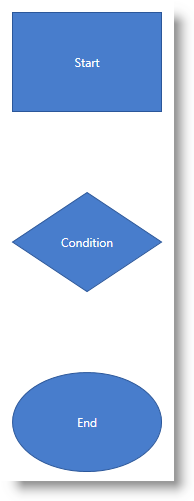
Configure the DiagramNode objects and add them to the xamDiagram control by adding the nodes to the Items collection of the diagram. The Items property is marked with the ContentPropertyAttribute.
In this example procedure, three differently shaped nodes are created. 1. Create the rectangle-shaped node.
Create the rectangle-shaped node (If the ShapeType property of the DiagramNode is not explicitly specified, the node type used will be “Rectangle” .) with a Height of 100px and Width of 150px , set its Content to “Start” and configure its Position on the diagram to be (200, 20) .
Set the Key property to a string identifier in order to be able to add connections from/to the node.
In XAML:
<ig:DiagramNode Key="node1"
Content="Start"
Height="100"
Width="150"
Position="200,20"/>
2. Create the rhombus-shaped node.
Create the rhombus-shaped node (Set the ShapeType property of DiagramNode to “Rhombus” ) with a Height of 100px and Width of 150px , set its Content to “Condition” and configure its Position on the diagram to be (200, 200) (This will place this rhombus beneath the rectangle created in step 2.1).
In XAML:
<ig:DiagramNode Key="node2"
Content="Condition"
Height="100"
Width="150"
ShapeType="Rhombus"
Position="200,200"/>
3. Create the ellipse-shaped node.
Create the ellipse-shaped node (Set the ShapeType property of DiagramNode to “Ellipse” ) with a Height of 100px and Width of 150px , set its Content to “End” and configure its Position on the diagram to be (200, 380) (This will place this ellipse beneath the rhombus created in step 2.2).
In XAML:
<ig:DiagramNode Key="node3"
Content="End"
Height="100"
Width="150"
ShapeType="Ellipse"
Position="200,380"/>
4. Add the three nodes to the xamDiagram control. In XAML:
<ig:XamDiagram x:Name="diagram"
Width="700"
Height="700">
<ig:DiagramNode Key="node1".../>
<ig:DiagramNode Key="node2".../>
<ig:DiagramNode Key="node3".../>
</ig:XamDiagram>
The following screenshot is a preview of what the diagram should look at this point.
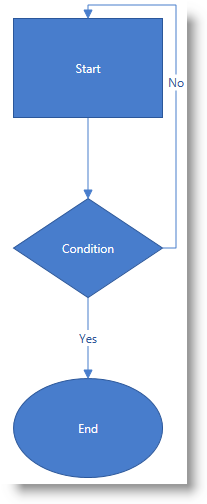
1. Add the connections between the nodes by configuring the connections as DiagramConnection objects with StartNodeKey and EndNodeKey properties set to the nodes that are being connected.
In this example procedure, you create three arrow-pointed diagram connections.
A. Create an arrow-pointed straight line connection between the Start and the Condition nodes.
To this end, set the StartNodeKey property of the connection to “node1” and the EndNodeKey property to “node2” . As by default the end cap of the connection already represents a filled arrow ( EndCapType= ” FilledArrow ” ), only its ConnectionType should be set to “StraightLine” to override the default setting for this property which is a right-angled line.
In XAML:
<ig:DiagramConnection Name="conn12"
StartNodeKey="node1"
EndNodeKey="node2"
ConnectionType="Straight"/>
B. Create an arrow-pointed straight line connection between the Condition and the End nodes.
Set the StartNodeKey, EndNodeKey, and the ConnectionType properties as in step 3.1.A. Set the Content property to “Yes” in order to specify the exit case in the activity flow example.
In XAML:
<ig:DiagramConnection Name="conn23"
StartNodeKey="node2"
EndNodeKey="node3"
ConnectionType="Straight"
Content="Yes"/>
C. Create an arrow-pointed right-angle line connection between the Start and the Condition nodes.
This connection represents the looping case in the activity diagram. Set its Content property to “No” . (The ConnectionType property has a default value of “ RightAngle ” , so no additional configuration applies for the type of the connection.)
D. Specify the exact positions on the nodes at which you want the connection to begin and end.
Specify the connections’ connector points by setting the StartNodeConnectionPointName and EndNodeConnectionPointName properties. Basically, by setting these properties to “Right” and “Top” , respectively, you specify that you want to draw a connection starting from the utmost-right connector point of “node2” and ending at the utmost-top connector point of “node1” (for details on the connector points, see xamDiagram Overview).
In XAML:
<ig:DiagramConnection Name="conn21"
StartNodeKey="node2"
EndNodeKey="node1"
StartNodeConnectionPointName="Right"
EndNodeConnectionPointName="Top"
Content="No"/>
E. Add the connections to the diagram.
In XAML:
<ig:XamDiagram x:Name="diagram"
Width="700"
Height="700">
...
<ig:DiagramConnection Name="conn12".../>
<ig:DiagramConnection Name="conn23".../>
<ig:DiagramConnection Name="conn21".../>
</ig:XamDiagram>
The following screenshot is a preview of what the diagram should look at this point.
2. (Optional) Add a stand-alone connection.
In this example procedure, you need to configure the connection representing the entry point of the activity flow diagram.
A. Create a connection and specify its StartPosition and EndPosition of to (175, 70) and (195, 70) , respectively.
In XAML:
<ig:DiagramConnection Name="connStart"
StartPosition="175,70"
EndPosition="195,70"/>
B. Add the connection to the diagram.
In XAML:
<ig:XamDiagram x:Name="diagram"
Width="700"
Height="700">
...
<ig:DiagramConnection Name="connStart"
StartPosition="175,70"
EndPosition="195,70"/>
</ig:XamDiagram>To verify the result, save and build the project. The diagram should look as shown the Preview.
Following is the full code for this procedure.
<ig:XamDiagram xmlns:ig="http://schemas.infragistics.com/xaml" x:Name="diagram"
Width="700"
Height="700">
<ig:DiagramNode Key="node1"
Content="Start"
Height="100"
Width="150"
Position="200,20"/>
<ig:DiagramNode Key="node2"
Content="Condition"
Height="100"
Width="150"
ShapeType="Rhombus"
Position="200,200"/>
<ig:DiagramNode Key="node3"
Content="End"
Height="100"
Width="150"
ShapeType="Ellipse"
Position="200,380"/>
<ig:DiagramConnection Name="conn12"
StartNodeKey="node1"
EndNodeKey="node2"
ConnectionType="Straight"/>
<ig:DiagramConnection Name="conn23"
StartNodeKey="node2"
EndNodeKey="node3"
ConnectionType="Straight"
Content="Yes"/>
<ig:DiagramConnection Name="conn21"
StartNodeKey="node2"
EndNodeKey="node1"
StartNodeConnectionPointName="Right"
EndNodeConnectionPointName="Top"
Content="No"/>
<ig:DiagramConnection Name="connStart"
StartPosition="175,70"
EndPosition="195,70"/>
</ig:XamDiagram>